Getting started with Unity's new Shader Graph Node-based Shader Creator/Editor (tutorial 2 - tiling, offsets, blending, subgraphs and custom channel blending)
Introduction (to the Tutorial Series):
I will be writing about my own experiences using Unity's new beta Shader Graph, part of its upcoming 2018 release (also in beta). The Shader Graph lets you create a variety of Unity shaders using nodes - not requiring you to write code.I will be writing about this journey over multiple posts, usually spaced about a week apart. Each post will be a short tutorial on how to use various node types to create different shader effects. And will include brief discussions on types of shaders and their uses, and later, how the Shader Graph compares with code-based shaders. I will try not to get overly technical, but will try to give you an idea of the complexity involved in shaders, from lighting to vertex and fragment manipulation.
Given the nature of beta software, expect the Shader Graph (and later tutorials) to vary from earlier ones that you can now find online. Even within my tutorials there will be changes if/when the beta evolves - including, if necessary, going over the basics again if something in the editor changes significantly.
I hope you find this tutorial useful. If you do, please be kind and click an interesting ad to help support this site. It really does help, believe me. And thank you, I'm grateful to you!
Other Tutorials in this Series:
Tutorial 1 - Setup and First 'Basic' Shader Graph (shader)Requirements:
You need Unity's 2018.1 beta. I am using 2018.1.0b7. You also need the latest Shader Graph. And we will start with the same Lightweight-Preview project from tutorial 1 using BasicShader (our shader graph) and BasicShaderMat (our material using our shader graph). You should have a sphere object using BasicShaderMat.For more information on setting up the beta and updating to the latest Shader Graph, please see tutorial 1.
Note: Update - this tutorial was based on Unity 2018.1.0b7 and Shader Graph 0.1.17. One change that has happened since that time is that you now create shader graphs by Assets->Create -> Shader->PBR Graph (or Sub Graph or Unlit Shader) instead of Assets->Create->Shader Graph.
Let's Start! Blending a Color and a Texture (Step 1):
In the first tutorial, we created a basic shader graph network. First, we connected a color to our Albedo input for our master PBR node. Then, we connected a texture to Albedo, instead of a simple color. We also looked at the Blackboard, where properties are created, and used our property nodes to expose properties to our shader user in the Unity editor.But what if we want to have color and texture into Albedo? In other words, we want to 'tint' the texture, or, if no texture is present, simply use a solid color.
There is only one input to Albedo, so we need to blend our texture and color nodes in some way.
Start up Unity 2018.1 beta and load your Lightweight-Preview project that you started in tutorial 1. Mine is called ShaderGraphTutorial. On my machine, it takes awhile to load. Load time-wise it's still faster than Unreal, so I just read email while I'm waiting.
Double-click BasicShader in the Project Assets folder or Single-click (select) BasicShader in Project Assets and click the Load Shader Editor button in the Inspector. The Shader Graph Editor should open in its own window.
Double-Click the Diffuse property in the Blackboard and rename it DiffuseColor.
In an empty area of the Shader Graph editor, Right-Click and Create Node. Then choose Artistic->Blend->Blend. A Blend node appears.
First, connect up the output of DiffuseColor to the Base(4) input of Blend. Then the RGBA(4) output of Sample Texture 2D to the Blend(4) input of Blend. Leave the Sample Texture 2D A(1) output connected to the Alpha(1) input of the PBR Master node. Finally, connect the Out(4) output node of Blend to the Albedo(3) input of the PBR Master node.

You should now see a colored version of the UI Sprite texture in the PBR Master, and the Preview window.
The Blend node is actually quite powerful. If you look closely you'll see a Dropdown menu. This menu lets you specify the type of blending to occur.
Try it out for yourself. Some blend modes won't seem very different than the default Overlay mode. But some are quite spectacular.

 Set the blend mode back to Overlay. Save the Asset (Save Asset button in the Shader Graph Editor) and look at your sphere in the Unity editor. It should have updated to reflect these changes. If you have left it with the same UISprite texture, but perhaps a different color, you should see that you now have a DiffuseColor that you can change, plus a DiffuseTexture.
Try changing the color and the texture.
Try changing the texture to 'none', leaving only the color. You should now see a solid color. You didn't have to worry about the texture sample still being connected in the shader graph. Everything blended as we wanted. If we want a texture, it's blended with the color. If we don't want a texture, we get a solid color.
Effect of Order on Blend Mode (Step 2):
But suppose you connected the Texture as the Base and the Color as the Blend? Try it. First, drag the RGBA(4) output to the Base (while it is still connected to Blend(4)). You'll see that you can have multiple connections from the same node connecting to the Blend node. In other words, you can blend a node with itself. Now drag the output from DiffuseColor to the Blend(4) node. It should automatically sever the connection between Blend and the Texture node and replace it with the DiffuseColor node. Now the Texture is the Base and the Color will be the Blend. With the same Overlay blend mode, you see it gives a different effect.
Why? It has to do with how blend modes are implemented. A blending is a mathematical operation that happens at the pixel level between two layers. In this case, the layers are a texture and a solid color. And while I cannot be sure how Unity has chosen to implement each blend mode (what mathematical equation they are choosing to use), in most blend cases, order matters. In the case of Overlay, usually the base layer will become lighter where it is light and darker where it is dark.
The equation is traditionally:
a = base, b = blend, f(a,b) = blended result
f(a,b) = 2ab if a < 0.5
f(a,b) = 1 - 2(1-a)(1-b) if a => 0.5
Again, I say traditionally because there is no requirement that I know of for graphics engine designers to follow this rule. But most likely will and do.
For a good introduction to blend modes, see this Wikipedia page.
One observation you should be making is that Unity's Standard Shader system is very powerful. (Again, I say it's more a system or a subsystem of the Editor rather than an actual 'shader' because it really is a piece of code that tailors a series of shader variants based on your input).
Why is it so powerful? If we had to duplicate the ability to choose a blend mode from a dropdown, such as what Standard Shader offers, we'd have a very complicated graph to hand each possible choice of the Blend mode. And we don't have the ability in the Shader Graph to create dropdown menus in the Inspector. That may change over time, but for now, if you need a basic shader - a shader that can be specified with the Standard Shader - then definitely use the Standard Shader!
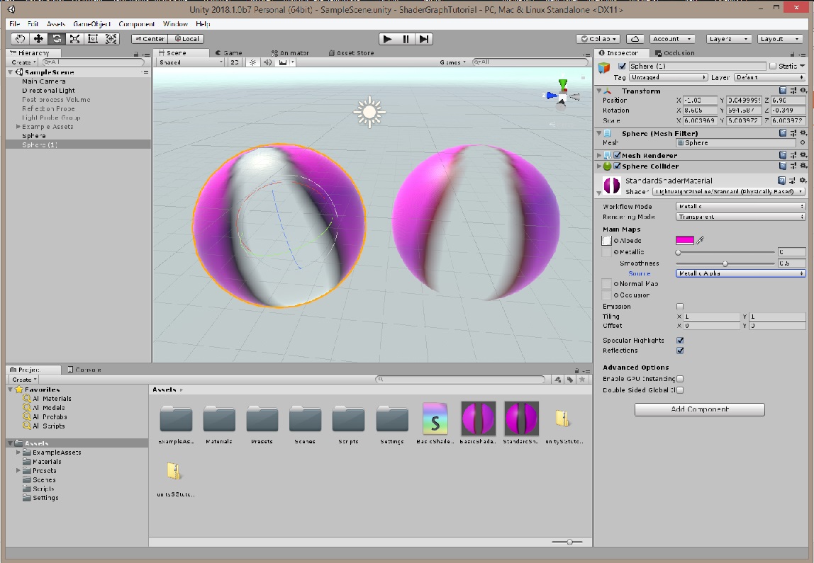
Standard Shader (LEFT) doing exactly what we just did with a shader graph (RIGHT).
Note: Even a code-based shader can't do dropdowns in the Inspector - though you can do properties, ranges and various types. If anyone has figured out how to do dropdowns, please let me know!
Writing a custom shader, either a code-based shader or a shader graph based shader, should be reserved for when the Standard Shader isn't flexible enough. Complex dynamic shaders, compute shaders, tesselation shaders all currently fall into this category - though that may change based on some of the nodes I'm seeing in the Shader Graph.
However, in later tutorials, we are going to explore dynamic shaders that change over time, and take a look at some of the artistic and procedural goodies that the Shader Graph offers.
Adding Texture Tiling (Step 3):
Regardless, understanding how basic shaders are created will help you understand how to break the mold when making your own custom shaders. For example, something that we take for granted is texture tiling - the ability to force a texture to tile horizontally and/or vertically across an object. The default behavior we've been seeing with the Shader Graph Editor is to stretch the texture across the surface of the object.Let's create the ability to tile.
Create two new properties of type Vector1 and name them HorizTile and VertTile. Set the Default value of each to 1 (one). But for UI comparison, set the mode of HorizTile to Slider and the mode of VertTile to Integer. Then for HorizTile, set the Min and Max values to 1 and 100. As you might expect, HorizTile will have a slider you can use in the Inspector that goes between 1 and 100, while VertTile will have an input box where you can type an integer value.
Drag each of the properties into an empty area of the Shader Graph editor.
Now, Right-Click and Create Node. Choose Channel->Combine.
Right-Click and create another node (Create Node). This time choose UV->Tiling And Offset.
Connect the output (Out(2)) of the Tiling and Offset node to the UV(2) input on the Sampler Texture 2D node.
You'll notice that the Tiling and Offset node has three possible inputs: UV(2), Tiling(2), Offset(2). We want to connect our two properties (HorizTile, VertTile) to the Tiling input. To do that, we need to combine them into one node. We use a Combine node to do that. Even though the Combine can take up to four channels (using the RBGA convention), it's OK to use less than that. It's a common shader trick to pass different data streams through RGBA channels.
Connect HorizTile to the R(1) input of Combine. Connect VertTile to the B(1) input of Combine. Think of it as R = X and B = Y.
Now connect the output of Combine (RGBA(4)) to the Tiling(2) input of the Sample Texture 2D.
 Save the Asset and try playing with the Default values on HorizTile and VertTile. You should see the texture changing form. To make it easier to see the tiling, change the Default texture (DiffuseTexture property) of Sample Texture 2D to a checkerboard texture, such as Unity's Default-Checkerboard.
For convenience, I have included a sample JPEG (testTexture) in the tiling zip file. Drag it into your Project Assets window to use it as your DiffuseTexture.
Add Texture Offset (Step 4):
Now Left-Click and Drag a selection rectangle around the HorizTile, VertTile and Combine nodes. Then Right-Click and select Copy.Now Right-Click and Paste. You now have the same nodes duplicated (but the copied Combine output is not hooked up to anything. You'll also note that you can have multiple copies of the same properties in the Shader Graph.
You do not get multiple copies of the actual properties (in the Blackboard).
 Go ahead and delete the duplicate HorizTile and VertTile nodes but keep the Combine node. Create two new properties (HorizOffset and VertOffset) that are Vector1. Drag those nodes out into the work area. Connect them, as you did with the tiling properties, to their own Combine node, and then connect the Combine node RGBA output to the Tiling and Offset node Offset(2).
To make things neater, change the VertTile property to use a Slider with a range of 1 to 100. And leave the HorizOffset and VertOffset properties at the defaults (0 value, and Default mode).

Note: Default type for Vector1 is Float. Even if you pick Integer, you'll see that (currently) it's still a Float. Click on BasicShader in the Projects-Assets and you'll see the shader information in the Inspector.
Custom Blending - the Concept and some pseudo-math (Step 5):
There's one problem with the way we've set up our blending. We are using Overlay and choosing to use the Color as the Base. The Texture is being overlaid onto the solid color. You'll see the issue if you choose DiffuseColor and set it to Full Transparency.
Nothing happens. Nothing changes. The alpha of DiffuseColor isn't feeding the PBR Master node. Only the Texture's alpha value controls the transparency. That's why we see the Color no matter what. It's something we want if there is no Texture, but it would be nice if it also contained transparency information.
We could reverse the two. Color as the Blend, and Texture as the Base, but we get a different effect when we do that. And in this case, we want a full tint. We want white areas to tint to our Color.
We might try combining the alphas. However, if you try it, you'll find that a simple Combine pretty much destroys the effect we want. Everything turns transparent if the Color goes transparent.
What we want is something like: if our Color is fully transparent, then only show the Texture. The less transparent our Color, the more Color is added as a Tint across the entire Texture. Or, if there is no Texture, we see just our Color. And just to complicate things more, if only using Color, then we want the Color to show transparency. (We want a transparent material effect.)
OK. First we might try different blend modes with a Blend node using first Color as the Base, then reversing the connections and trying Texture as the Base. I tried that and didn't find any combination that I liked. So now we need a custom solution.
Let's do a bit of pseudo-math.
Color + Texture(none or fully transparent) = Color (with any inherent Color transparency)
Color + Texture = Color Tinting of Texture (including white areas). Color amount should be less if it is transparent.
So what it appears we should do is add a proportional amount of Color to the Texture. The proportion of color is determined by the transparency of the color. The more transparent the color is, the less we add.
In our RGBA system, if alpha is 0, then the object is transparent. If alpha is 255, it is opaque.
So what we need to do is take a fraction of each channel (RGB) based on A (alpha) and ADD that to the Texture RGB pixels.
We're going to CLAMP the alpha range from 0-255 to 0-1. Then we can multiple it as a fraction against the RGB values.
So it sounds like our second equation would work. It becomes:
fraction of Color + Texture = Color Tint to entire Texture (even transparent areas)
But the first equation, where the Texture is either 'none' or fully transparent (there but unseen) would not work. Why? Because we are feeding the Texture's alpha channel to the PBR Master node.
In the case of no (or full transparent) Texture, we need the alpha from the Color to dictate the transparency effect. But we only want it to dictate transparency in that one situation. Otherwise, we want the texture to dictate what the transparency is.
The solution is to add the Color alpha channel to the Texture's alpha channel. If both are full transparent, then we have transparency. If Color is full opaque, then as a Tint effect, it will make any Texture transparent areas opaque. It would be like overlaying a solid sheet of paper (Color) over a piece of cellophane (Texture).
Our two equations:
alpha(Color, clamped(0,1)) * Color(RGB) + Texture(RGB) = Color Tint to entire Texture (even transparent areas)
alpha(Color) + alpha(Texture) = alpha to feed to PBR Master input A(1)
Custom Blending - Create the Nodes (Step 6):
So let's see if this works.- We will need to split our DiffuseColor into its RGBA components.
- Sample Texture 2D already gives us outputs split into RGBA components.
- We will need a way to Clamp the alpha channel from 0-255 to 0-1.
- We will need a way to Multiply the clamped alpha value and each Color RGB.
- We will need a way to Add the resulting RGB from Color to the RGB from Texture.
- We will need a way to Add the Color alpha to the Texture alpha. The result will feed the PBR Master A(1) input.
 First, let's tidy up the workspace. Left-Click and Drag select the two tiling property nodes, the offset property nodes, the two Combine nodes and the Tile and Offset node. Right-Click and Convert to Sub-graph. If needed, move other nodes out of the way first, to avoid selecting them.
Save the sub-graph as TileAndOffsetSub.ShaderSubGraph.
The Tiling and Offset properties you created in the Blackboard are not redundant (even though they are also contained in the subgraph and appear as inputs.) Pull out the 4 properties as nodes again and hook them back up to their subgraph input counterpart. If you don't, if you just delete them, then you won't see them as settable parameters in the Inspector anymore.
Save the shader graph workspace. (Save Asset button in the upper left of the Shader Graph Editor.)
Note: You can Left-Click Drag a selection around a group of nodes, then Left-Click Drag them as a unit. To move the entire graph, use the Middle Mouse button. (Middle Mouse Click and Drag.)
1. Delete the Blend node.
2. Right-Click and Create Node. Channel->Split. Connect the output of DiffuseColor to the input of Split.
3. Right-Click and Create Node. Math->Range->Clamp. Connect DiffuseColor A(1) to Clamp In(1). Leave Min and Max at 0,1. This clamps the color's alpha range to between 0 and 1.
4. Right-Click and Create Node. Math->Basic->Multiply. Connect the Clamp Out to Multiply A(1). Connect Split R(1) to Multiply B(1).
5. Right-Click and Create Node. Math->Basic->Add. Connect Multiply Out to Add A(1). And connect Sampler 2D Texture R(1) (the Red channel) to Add B(1).
6. Right-Click and Create Node. Channel->Combine. This is how we will reassemble the RGB values back into a color value. Connect the output of Add to the R(1) of Combine. Connect the Combine RGBA(4) to the Albedo of the PBR Master node.
7. Right-Click on the Multiply node and select Duplicate. Create two duplicates.
8. Right-Click on the Add node and select Duplicate. Create two duplicates.
9. Now, hook up the Green and Blue channels the same way. Repeat steps 4 and 5 (but use G(1) or B(1) instead of R(1).)
10. Save Asset to save the shader graph.
 You should end up with a graph looking like this. If we use the UI Sprite as our texture, then click Color on DiffuseColor, we should see the transparent areas of UI Sprite fill up with our color as we change Color transparency from 0 to 255. The alpha channel is working as we designed it.
Custom Blending - the Weighting Problem (Step 7):
However, there is a problem. Instead of seeing the white areas of the texture turn Red as Color goes from transparent (0) to opaque (255), it just stays white. Why? We expected it to become red. We want it to appear that we've overlayed a solid color on the Texture when Color is fully opaque.It turns out the problem is weighting. We are using the Color alpha to weight how much Color's RGB values contribute to each combined (blended) pixel's color. But that just means we are adding extra color to what is already in the Texture.
For example, if our Color is (255,0,0) and we add it to a white pixel in the Texture (255, 255, 255), the result is clamped to a max value of 255 for each channel and we get (255+255, 255, 255) = (255, 255, 255) when clamped. In other words, we're maxing out at the strongest value.
What we need is to also weight the Texture's channel values (R,G,B) based on the alpha of the Color. The more Color opaqueness we have, the more we want Color and the less we want the original Texture color. The less Color, the more Texture color we want.
Here is our new equations:
alpha(Color, clamped(0,1)) * Color(RGB) + (1-alpha(Color, clamped(0,1)) * Texture(RGB) = Color Tint to entire Texture (even transparent areas)
alpha(Color) + alpha(Texture) = alpha to feed to PBR Master input A(1)
So we need to add two more nodes to each of our channels.
1. Right-Click and Create Node. Math->Basic->Subtract. Keep the little default connection on A(1) and make sure it's set to the value 1 (one). Connect the Clamp Out to the Subtract B(1). We now have (1 - the clamp result).
2. Right-Click and Create Node. Math->Basic->Multiply. Connect the output of Subtract to Multiply A(1). Connect Sample Texture 2D R(1) (the Red channel) to Multiply B(1). We now have (1 - clamped value) * Texture Red channel.
3. Connect that Multiply Output connection to the Add node B(1). The Add A(1) takes the previous Multiply node. This new input to B(1) replaces what we had before, which was the Sample Texture 2D R(1) (red channel).
4. Create duplicates of these two new nodes (Subtract and Multiply) and repeat steps 1-3 for the Green and Blue channels.
5. Save Asset to save the shader graph.

Shown with Color Picker active as we move from fully transparent Color to medium to fully opaque Color.
Graph showing no color and only texture (with transparency correct for texture)

Graph showing mixed color (tint) and texture (transparency of texture filling in with some color)

Graph showing color fully opaque. Texture is gone. Solid color.
Conclusion and Next Steps:
Now if we try out the graph, we should see the transparent areas AND the non-transparent areas turn our color when we make our color fully opaque. When the color is fully transparent, we just see the texture. When it's in-between, we see a tinted texture using our color. When we compare it to the Standard Shader, we get a different result.
There's only one problem left. DARN IT!
Everything works when we have a texture selected. If the Color is fully transparent, the Texture shows. If the Color is fully opaque, the Texture is overwhelmed.
 But when there is NO texture ('none'), Color set to alpha at 0 will yield a gray texture.
Welcome to the headaches involved in shaders. <Heavy Sigh>
But how do we fix this?
Frankly, I don't know right now. I have some ideas, but would like to find a more elegant solution. Or perhaps use it as a way to investigate flow control nodes. We'll see.
So we have these questions:
1. Is this behavior normal or a bug? Either way, we want to find a way to correct for it.
2. Is there a cleaner or more elegant way to do the component by component multiplication, addition and subtraction? I haven't investigated even a small amount of the number of nodes available, so there might be.
3. Can we turn parts of this graph into subgraph units for a) reuse and b) to simplify the look of the graph? We need to understand the use of subgraphs more fully.
I'll work on these questions for later tutorials. For now, just use a texture in the Texture spot. And not only that, but look at Normal maps and creating them on-the-fly, along with some time-based animation.
I hope this tutorial is helpful! Thanks for reading!
Next Tutorial:
Getting started with Unity's new Shader Graph Node-based Shader Creator/Editor (tutorial 3 - Normal maps, Faux-Water Effect, Animation with Time and Noise)copyright 2018 cg anderson - all rights reserved


Comments
Post a Comment