Getting started with Unity's new Shader Graph Node-based Shader Creator/Editor (tutorial 4 - updating to next beta and the Dissolve shader via turning Cg/HLSL code into node-based graph)
Introduction (to the Tutorial Series):
I will be writing about my own experiences using Unity's new beta Shader Graph, part of its upcoming 2018 release (also in beta). The Shader Graph lets you create a variety of Unity shaders using nodes - not requiring you to write code.I will be writing about this journey over multiple posts, usually spaced about a week apart. Each post will be a short tutorial on how to use various node types to create different shader effects. And will include brief discussions on types of shaders and their uses, and later, how the Shader Graph compares with code-based shaders. I will try not to get overly technical, but will try to give you an idea of the complexity involved in shaders, from lighting to vertex and fragment manipulation.
Given the nature of beta software, expect the Shader Graph (and later tutorials) to vary from earlier ones that you can now find online. Even within my tutorials there will be changes if/when the beta evolves - including, if necessary, going over the basics again if something in the editor changes significantly.
I hope you find this tutorial useful. If you do, please be kind and click an interesting ad to help support this site. It really does help, believe me. And thank you, I'm grateful to you!
Other Tutorials in this Series:
Tutorial 1 - Setup and First 'Basic' Shader Graph (shader)Tutorial 2 - Tiling, Offsets, Blending, Subgraphs and Custom Channel Blending
Tutorial 3 - Normal maps, Faux-Water Effect, Animation with Time and Noise
Requirements:
You need Unity's 2018.1 beta. I am using 2018.1.0b7. You also need the latest Shader Graph Editor. And we will start with the same Lightweight-Preview project from tutorial 1 but will be creating a new shader graph called NormalShader. The previous shader graph BasicShader should be renamed TintShader. You should have a sphere object using NormalShaderMat.For more information on setting up the beta and updating to the latest Shader Graph Editor, please see tutorial 1.
Note: Update - this tutorial was initially using Unity 2018.1.0b7 and Shader Graph 0.1.17. One change that has happened since that time is that you now create shader graphs by Assets->Create -> Shader->PBR Graph (or Sub Graph or Unlit Shader) instead of Assets->Create->Shader Graph. At the end, I added an update about my experiences with 0b10.
Let's Start! First, Updating to Latest Unity Beta and Shader Graph (Step 1):
At the time of tutorial 3, I noticed that the shader graph had an update ready. And the Unity beta had also updated. So for this tutorial, I will first update my beta to the latest and proceed from there. Hopefully, nothing will break!To be cautious, I updated Unity Hub first. Here's the lesson I learned. Unity Hub immediately lost track of the fact that I already had a beta Unity build on my desktop. Caveat: if it happens to you, remember you can search your computer for where you installed the beta and then Hub will have it again.
Second, I chose to download and install the latest Unity beta via the Hub, which means I kept the other beta.
Finally, I opened my tutorial project and the Package Manager and let it update the Shader Graph package to the latest. Unfortunately, I didn't update the Render-pipelines.lightweight first. So I tried to undo (delete) the Shadergraph update. Unfortunately, that deleted it permanently and I couldn't find a way to get it back! I ended up having to create an entire new Lightweight-preview project and transfer all my tutorial assets to that project. That was the only way I could get back to a workable solution.
The final result is that while I did download the latest Unity beta, I did not upgrade to the latest shader graph for this tutorial. I didn't even realize it until the end when I checked. The project I created did not automatically use the latest and greatest shader graph and render-pipelines.lightweight packages.
So this tutorial was done on the old beta with 0.1.28 render-pipelines.lightweight and 0.1.17 shadergraph! I couldn't get to the shader graph version that I used last time either. It is something I wish was different. It would be nice to be able to specify the version you want from the package manager, and be able to 'undo' if you make a mistake.
Very frustrating!!
Anyway, I will update to the preview 1.1.1 version between now and the next tutorial I write, and see if that has any effect on the oddities I found with clipping in this tutorial. It may not, but if it does I'll post an update with what I find.
The Dissolve Shader - Start with a Code-based Shader (Step 2):
We're going to start with a code-based shader. Why? Because it's a great way to show how to transfer between code and nodes. Also, this is something a shader writer will typically have to do - take some shader from one environment (be it code like Cg, HLSL or GLSL, or a node network like Unreal's Material Editor system) and find a way to turn make it work in another system. Sometimes, it would be very, very complicated to transfer. And there is no guarantee the node-system would support all the functionality of a code-based system. But it's still a good exercise and this is a simple shader.The dissolve shader has been around likely as long as shaders have. At it's core it is simply a dissolve effect where the object seems to dissolve away as randomly placed holes appear and expand. If you search the Internet, you'll find lots of blog posts and github accounts dedicated to this shader - some with variations, others just copies of earlier posts on the subject.
I'll go with a simple dissolve shader. I'm going to use the one I found online (years ago and pre-dating most blog posts on the subject.) So this isn't a shader that is original on my part, and I freely give the credit to the author. Whether the author designed it or was using someone else's design I don't know. But it's important, even in the free wheeling Internet, to ALWAYS give credit when referencing someone else's work and of course, always observe any copyright (or copyleft) instructions.
You can find the dissolve shader I'm using here. It's part of the UnifyCommunity UnifyWiki focused on unity3d (not official) and is from around 2011. It uses a Creative Commons license.
Official description: A simple "dissolving" surface shader for Unity 3. It uses an image as guidance to remove pixels - with randomly generated clouds or noise, it generates a neat dissolving effect. This shader should work with most graphics cards.
Here is the Unity-based shader code. Unity uses a blend of Cg and HLSL with its own macros added.
// simple "dissolving" shader by genericuser (radware.wordpress.com)
// clips materials, using an image as guidance.
// use clouds or random noise as the slice guide for best results.
  Shader "Custom Shaders/Dissolving" {
    Properties {
      _MainTex ("Texture (RGB)", 2D) = "white" {}
      _SliceGuide ("Slice Guide (RGB)", 2D) = "white" {}
      _SliceAmount ("Slice Amount", Range(0.0, 1.0)) = 0.5
    }
    SubShader {
      Tags { "RenderType" = "Opaque" }
      Cull Off
      CGPROGRAM
      //if you're not planning on using shadows, remove "addshadow" for better performance
      #pragma surface surf Lambert addshadow
      struct Input {
          float2 uv_MainTex;
          float2 uv_SliceGuide;
          float _SliceAmount;
      };
      sampler2D _MainTex;
      sampler2D _SliceGuide;
      float _SliceAmount;
      void surf (Input IN, inout SurfaceOutput o) {
          clip(tex2D (_SliceGuide, IN.uv_SliceGuide).rgb - _SliceAmount);
          o.Albedo = tex2D (_MainTex, IN.uv_MainTex).rgb;
      }
      ENDCG
    }
    Fallback "Diffuse"
  }
The Dissolve Shader - Breaking Down the Code into Nodes (Step 3):
Most of the framework of the code will be ignored. What we are looking for are the properties being used and the meat of the shader, what is being processed and passed along. So beginning at the top, we see that the shader is called "Custom Shaders/Dissolving". This means it would be in the shader menu under Custom Shaders and named Dissolving. Since currently shader graphs are all under graphs, we ignore the directory information but keep the name.Create a new shader graph and name it Dissolving. Create a new Material and call it DissolvingMat. Then open the shader graph (Dissolving) up in the Shader Graph Editor.
The next thing we see in the code sample is a list of properties. These are identical to Property nodes that we need to create for our graph, though we don't need to use the "_" (underscore). The only problem here is that we aren't sure from the Properties section what the TYPE of the property is - the hint we get is 2D and Range. So we scan down and find the same names in the SubShader body and here we see that both MainTex and SliceGuide are sampler2D. SliceAmount is a float. sampler2D in graph terms is a Sample Texture 2D.
Create three properties for the graph and drag them into the work area.
MainTex, which is a texture.
SliceGuide, which is a texture.
And SliceAmount which is a Vector1 Range which goes from 0.0 to 1.0 with a default of 0.5.
The default of white on both textures can be ignored. The shader graph default is fine.
Now, some information to note. Starting at the SubShader (the actual code of the shader), we see it's rendertype is Opaque. That simply means we don't need to turn on Transparency for this shader.
Except, we actually will, since we will be trying to create the ability to 'clip' or to simply do an 'alpha cut-out'. (More on that later.)
We also see that culling is off, meaning we want the backside of any objects. We do not want the rendering process (pipeline/engine) to remove faces that aren't directly seen by the camera. If you think about what we are doing - dissolving an object - it makes sense. As the dissolve progresses, we want to see the object's backside through the holes being created by the dissolve effect.
CGPROGRAM just tells the compiler where the actual Cg code starts (and ends with ENDCG.) You can ignore it.
The #pragma line is specifying some advanced features the Unity uses in compiling the shader, which we will ignore for now. Just note the part about shadows, as it would be important if the object that will use the shader needs to cast or receive shadows. For this tutorial, we aren't going to worry about.
Note: I saw that someone reported a bug to Unity saying that cut-out shader graphs aren't doing shadows correctly. We aren't doing shadows here, but keep that in mind if you are using them. No idea when that bug will be fixed or if it was reproduced by Unity.
The input structure (struct Input) is telling us that we will be using UV coordinates to access each texture. That is perfectly normal, by the way. And we will be using a floating point value as a parameter for the slice amount. We see this structure because this code is for a surface shader that will likely be turned into individual vertex and fragment shaders by Unity.
Then we see the variables that correspond to our Properties. Again, we already covered that when we created three shader graph Property nodes.
The next line (void surf(.....)) is the function that processes the incoming vertex using the properties we've specified and then outputs the result into an output structure that will be passed down the rendering pipeline.
We have two lines, a clip line, and an output to Albedo. This is the heart of the translation from code to nodes.
First, both lines use tex2D. This just means go into the SliceGuide texture (the first parameter, such as _SliceGuide or _MainTex) at the specified Input UV coordinates (IN.uv_XXX) and fetch the RGBA value at that spot.
The .rgb at the end simply says we are only interested in the R,G, and B values in that order. We don't care about the A (alpha) value.
So now let's work out the rest of each line.
clip(tex2D (_SliceGuide, IN.uv_SliceGuide).rgb - _SliceAmount);
This means call the clip function on the result of the R, G, and B values AFTER you have subtracted off the float value of SliceAmount from each one. The Red, Green and Blue values run from 0 to 1 here - not 0 to 255. They are normalized to 1 in this case.
So we will have to create a node network that gets the RGB value from a texture, splits out the R, G and B channels separately, then subtract our SliceAmount property from each one. Then clip the result.
Likewise, with the output to Albedo line.
o.Albedo = tex2D (_MainTex, IN.uv_MainTex).rgb;
We want to sample the texture at that UV point in MainTex. Get the RGB values (not the Alpha) and take that RGB value and feed it into the Albedo channel as an output. In our case, that means simply feed it into the Albedo input of our PBR Master node.
But wait! What does clip do? And how does clipping the SliceAmount texture effect the MainTex texture? The MainTex texture is our object's texture. It's the texture where we want to see dissolving holes appear.
Let's talk about clip before we start creating nodes and hooking them up.
The Dissolve Shader - What is Clip() (Step 4):
The clip() function comes from both Cg and HLSL. It's an intrinsic function that basically simulates a clipping plane. What is within the plane is rendered, what is not is discarded. It helps optimize the rendering pipeline. When you call clip, you are basically telling the pipeline to discard processing that particular pixel if the pixel's value is less than zero. So this is more than just making the pixel transparent, because even a transparent pixel is passed along the pipeline and may or may not still have some effect. This is outright "get rid of it!"So what clip is doing here is checking the result of the subtraction (per R, G, and B) of .rgb with the float SliceAmount. If any of the three (Red value - SliceAmount, Green value - SliceAmount or Blue value - SliceAmount) are less than zero, then that entire pixel is discarded.
For those that like code, it's equivalent to this: (formula grabbed from this author/link)
void clip(float4 x) {if (any(x < 0))discard;}
What that means is that the MainTex texture is also affected. If the pixel is thrown out of the pipeline, then the MainTex texture at that pixel also won't be processed. In other words, we get a hole - a dissolve - for that object using that shader.
Here is a great OpenGL GLSL example of what is happening (ignore the code and look at the pictures. The red spots are where the discarding will happen in the texture). Basically, we are discarding that pixel. Remember, the rendering pipeline still will write to that pixel on the screen (but for other objects, etc.). It's only our dissolving object that doesn't write to that pixel.
For a Unity video tutorial discussing clipping (for cut-out effects) and displacement (but using code based shaders), click here.
An alpha cutout, on the other hand, keeps the pixel for that object but makes it transparent.
Whether one method or the other (clip vs cutout) is the better choice for optimization isn't clear cut. Frankly, it depends on the architecture. Most of the time, clip should yield a small performance advantage, but you need to test the shader, and test it in context (not just the device but the entire app) to determine whether you use clip or cutoff (or just don't care!)
So, the first question is: Does the Unity Shader Graph Editor system have a Clip node (or an equivalent, such as Discard) ?
The Dissolve Shader - Finding the Right Nodes (or Making SubGraphs, if possible) (Step 5):
Well, the answer to the question of whether the Unity Shader Graph Editing system has a clip() function (or a discard) function is "no." However, there is a clipping function based on alpha, as it turns out. On the PBR Master node (or Unlit Master as well) there is an AlphaClipThreshold(1) input. By looking once more at Matt Dean's original post, which is big on pictures but less so on actual documentation, it appears that based on what value Alpha(1) is set to, you can clip that pixel if the incoming value to AlphaClipThreshold is less than that value.That's what I thought initially. However, it doesn't seem to be working the way I expect. For example, if I use a simple particle texture (solid center with gradient in a circle spreading out to full transparent) as my input the AlphaClipThreshold. And I set Alpha to 0. My assumption was that if the incoming pixel alpha value was equal or less than 0, then clip the pixel.
But here's what I got.
And no, before you ask, just setting Alpha to 1 (the opposite of 0) made the entire texture opaque (no cutout at all).
Here was what I was expecting, something similar to what would happen if the pixels just went transparent. I fed the particle texture alpha into the Alpha channel (as I would do if I just wanted the pixels to be transparent, not clipped.)
Note: To show transparency I had to change the PBR Master Node from Opaque to AlphaBlend in the dropdown.
So without documentation as to what AlphaClipThreshold is actually doing and how it relates to the Alpha input, I can only guess that it's doing the opposite of what I was expecting!
So in the dissolver shader code, we were going to subtract SliceAmount from the RGB values of the SliceGuide texture. Normally, had my assumption been correct, that would have been RGB value - SliceGuide value, but now we need to reverse that to SliceGuide value - RBG value.
So, first create two Sample Texture 2D nodes and hook up the MainTex property to the Texture(1) input of one, and the SliceGuide property to the Texture(1) of the other. Then connect the MainTex Sample Texture 2D node to the Albedo input of the PBR Master node. It should look similar to the previous images.
Note: Previous tutorials went into how to create nodes and properties, and how to navigate/search the Create Node context menu. This tutorial assumes you are now comfortable doing that.
As for the SliceGuide texture node, create a Combine node as well as a Subtract node. Hook the R, G and B outputs from the SliceGuide Sample Texture 2D outputs to the R, G, B inputs of the Combine node. We are going to be faithful to the original shader and not use the alpha channel. It may not matter, but just in case, we will avoid the alpha channel.
Now hook the Combine node output (RGBA(4)) to Subtract's A(4) input. And the SliceAmount property node to Subtract's B input. This is the way I had assumed it would work. I want to show you the effect. This is essentially the equation .rgb - SliceAmount.
Make sure the PBR Master node is set back to Opaque (not AlphaBlend). And connect the output of the Subtract node to the AlphaClipThreshold input of the PBR Master node.
Set SliceAmount default value to zero (0). Remember, the assumption was that SliceAmount would be subtracted from the RGB values of the guide texture, and if the result was less than zero, the pixel should be clipped.
You should see something like this.
So until Unity clarifies how AlphaClipThreshold actually works, more than simply posting a picture, it's hard to understand how to use it effectively.
Meanwhile, let's reverse the subtraction. Change the graph so that SliceAmount feeds the A input and the SliceGuide Combine RGB output feeds B. Now we have SliceAmount - .rgb.
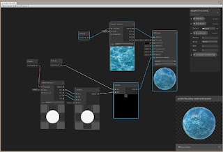 With SliceAmount left at zero, we see what (I think) is more expected. In other words, nothing changes.
Now, as the SliceAmount value goes from zero to one, the size of the clipping area also goes up (instead of down). Still, as you can see when you play around with the SliceAmount value, the effect is not linear. There is a huge amount of clipping that happens between 0 and 0.1, and then very little from 0.1 to 0.9. And in the case of the Knob texture, you even have some amount 'not clipped' when you are fully at SliceAmount of one (1). The particle texture shows a similar effect.
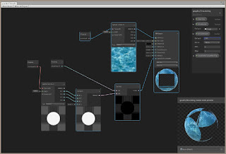
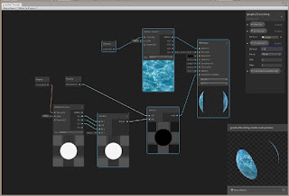
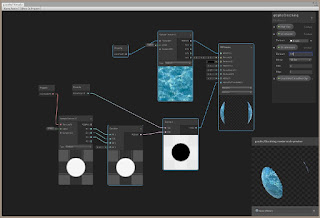
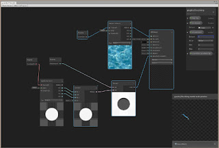
Overall, the result is not very satisfactory. However, it does come close to the code-based Dissolver.
Note: If you look closely, you'll realize that I didn't have to create a separate Subtract node for each R,G,B channel. This was something I didn't realize earlier. The Subtract node automatically updated to handle one, two, three or even all four channels at once and output a four (three, two, or one) channel result. Pretty cool, and similar to other node based shader systems like Unreal's Material Editor.
If you Save Asset (save your shader graph) and return to the Unity editor. You can now move the SliceAmount slider to see the different effect of the dissolve. This shader isn't animated on its own (i.e. with Time or Sine Time). You would increase or decrease the SliceAmount programmatically. You would write a script that updates the SliceAmount parameter - usually during Update() call and incrementally increase the amount to get the dissolve rate you wanted.
However, if you want, you can also animate the shader using Time or Sine or Cosine Time (for a wave lapping effect). You'll have to be careful. Remember the SliceAmount isn't linear in this shadergraph.
For fun, I updated the graph to use Sine Time to get a cyclical wave lapping effect. To keep the amount of increase small over time, I'm just multiplying SliceAmount by Sine Time and adding that to itself (SliceAmount).
In other words, SliceAmount = SliceAmount + SliceAmount*Sine Time.
And instead of directly feeding SliceAmount into the Subtract node (the A input), I'm feeding the result of that Add/Multiply instead. Like the image above shows. (I also changed the SliceGuide texture to a more random pattern, which I found in Standard Assets. It's just a particle system texture.)
Animation cyclic wave effect in the main editor.
The Dissolve Shader - Get a Good Night's Sleep, then Try Again (Step 6):
This step was added one day after posting this tutorial.
Still bothered by what I was seeing using the PBR Master node's AlphaClipThreshold input, I decide to do some tests. I would feed the SliceGuide texture straight into AlphaClipThreshold (no modifications) and manipulate the Alpha value. This is what I saw in Unity's blog post picture.
After some random playing, I got smart and noticed that it seemed to be responding to a grayscale image (not a transparent one). I created a test texture with Black, Gray, Light Gray and White on a white background. This test texture had no transparency whatsoever.
Take a look at what I found. SliceAmount is set a zero (0) so it has no effect on the SliceGuide pattern here. (Ignore the other nodes. I left them in place but am not using them.)
Alpha set to 0. The Black bar is shown (as the MainTex pattern), though there is some transparency added around the 'B' which was in white. Gray and white cause transparency in the main texture.
Alpha set between 0 and 0.5. Gray now begins to come through, with 0.5 Alpha showing all of it. Again, white and light gray make the main texture transparent.
Alpha set between 0.5 and less than 1. Now only white areas cause transparency in the main texture.
Alpha set to 1. Nothing is transparent.
Alpha set to 0.2. Notice that some gray is beginning to bleed through (despite the gray being a solid color.)
Particle pattern with alpha at zero gives the inverse of the pattern - black areas become opaque and white/gray areas become transparent. Setting alpha to 1 just gives a solid main texture (no effect from particle pattern on result.)
What seems to be happening is not a clip() function, or at least not the kind I was expecting. It seems to be some sort of blending clip that uses not just the texture feeding AlphaClipThreshold, but also the Albedo texture. The result seems to be controlled by some blend result that is compared with the Alpha value you set. I took a stab at trying to figure out which blending function they were using by trying to create a "truth table" with various AND, OR, XOR combinations. But I couldn't determine the exact equation based on the information I had.
If someone else loves truth tables, please feel free to solve the puzzle and let me know!
As a result, what we did by reversing the subtracting and trying to make the effect work according to a SliceAmount that goes from zero (no holes) to one (extreme dissolve) is a suitable result given the unexpected behavior (from my point of view, of course) and interaction of AlphaClipThreshold, Alpha, MainTex and SliceGuide.
Conclusion:
I was going to also show how to do this same effect using nodes and using transparency (not clipping). And I was going to add a Boolean node to let the user choose between the methods. After working through using clipping, I realized that this would make the graph overly complicated AND there does NOT seem to be any obvious way to force a PBR Master node to change from Opaque to AlphaBlend. AlphaBlend would be required in order to use transparency.So, while such a thing would be easy to do with code (Cg/HLSL), I could not find a way to do both methods within the same shader graph. It doesn't mean that you can't, since apparently you can have multiple PBR Master nodes in your graph. It just means that I couldn't discover (yet) a way to do it. Right now, it appears that you would have to create two shader graphs.
Overall, the goal was to show you how to start transferring a code-based shader to a Unity Shader Graph based node shader. In this case, even though it was a simple code-based shader, because of my issues with understanding how the AlphaClipThreshold/Alpha inputs work in Unity's node system, the shader turned out more complicated than expected. This isn't a typical case though. And possibly with proper documentation, it wouldn't be an issue.
But it does show that documentation is crucial. It also demonstrates that some macros and intrinsic functions found in code-based shaders may not be available in a node-based system (or will behave differently than you might be expecting) - and you will have to find creative ways to get the same effect. It also reminds us that Unity's system isn't as mature as compared to say, Unreal's Material editor, but hopefully, they will continue to add more features (and documentation) in order to expand its capabilities and ease of use.
Still, I hope this was helpful. Thanks for your support!
Update (as promised - result of updating to latest shader graph, lightweight pipeline, and then latest Unity beta):
This was added one day after tutorial was originally published.
Assumption is "do not use 1.1.1-preview with the 0b7 beta version."
I then tried to open the tutorial project in the latest Unity beta. (2018.1.0b10). (I set this beta as the preferred in Unity Hub, then tried to open the tutorial project.) It gave me some warnings since the project was created in an older version, and informed me that the package manager manifest is now in the Packages sub-directory.
The tutorial comes up but my objects (using my dissolve shader) are pink now, as is the Dissolving Material icon. I open up the Shader Graph and everything works.
However, the ability to designate a mesh for the preview is now gone. You are stuck with the sphere, which is unfortunate since it was easier using the Plane to see the true effects of AlphaClipThreshold. Now, I have to go back to the main Unity editor and create a Plane using the shader if I want to see the effect on a flat surface (similar to the texture itself).
Saving Asset and going back to the Editor, my shaders now work. Though the material icon is still pink. Opening another shader in the Shader Graph Editor then saving it makes the pink go away on the Dissolving Material.
Such is beta software, I guess.
Next Tutorial:
Getting started with Unity's new Shader Graph Node-based Shader Creator/Editor (tutorial 5 - Exploring Fresnel/Color Rim and Update on Vertex Displacement Attempts)copyright 2018 cg anderson - all rights reserved


Comments
Post a Comment